| Sign In | Join Free | My himfr.com |
|

hanse-john electronic Co.,Ltd.
Quality, quality, quality Based on honesty, innovation and far-reaching hanse-john electronic Co.,Ltd.
Active Member
5 Years
- Home
-
Products
- SMD Filter(13)
- Ceramic Bandpass Filter(10)
- Ceramic Low Pass Filter(11)
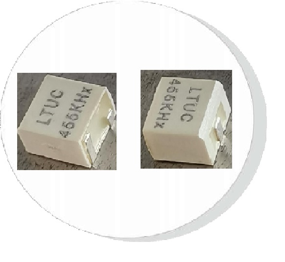
- 455 Khz Ceramic Filter(39)
- Ceramic Discriminator(13)
- Ceramic Resonator(11)
- Crystal Filter(10)
- Crystal Resonators(7)
- Saw Bandpass Filter(10)
- Surface Acoustic Wave Resonator(7)
- Piezoelectric Ceramic Actuator(8)
- Ultrasonic Atomizing Transducer(11)
- Piezoelectric Ceramic Sensor(7)
- Ultrasonic Welding Transducer(7)
- Piezoelectric Ceramic Transducer(4)
- Microwave Bandpass Filters(17)
- Microwave Low Pass Filter(15)
- About Us
- Quality Control
- Contact Us
- Get Quotations