Sign In | Join Free | My himfr.com
Home > 455 Khz Ceramic Filter >

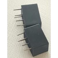
CFUKG455KH1X R0 0.455Mhz 1dB Electrical Line Filter

    Buy cheap CFUKG455KH1X R0 0.455Mhz 1dB Electrical Line Filter from wholesalers
     
    Buy cheap CFUKG455KH1X R0 0.455Mhz 1dB Electrical Line Filter from wholesalers
    • Buy cheap CFUKG455KH1X R0 0.455Mhz 1dB Electrical Line Filter from wholesalers
    • Buy cheap CFUKG455KH1X R0 0.455Mhz 1dB Electrical Line Filter from wholesalers
    • Buy cheap CFUKG455KH1X R0 0.455Mhz 1dB Electrical Line Filter from wholesalers
    • Buy cheap CFUKG455KH1X R0 0.455Mhz 1dB Electrical Line Filter from wholesalers
    • Buy cheap CFUKG455KH1X R0 0.455Mhz 1dB Electrical Line Filter from wholesalers

    CFUKG455KH1X R0 0.455Mhz 1dB Electrical Line Filter

    Ask Lasest Price
    Brand Name : HM
    Model Number : ceramic filter 455khz CFUCG455KH1X-R0,Alternative model:JGK01-1397B
    Certification : Rohs,ISO
    Price : €0.7
    Payment Terms : Western Union
    Supply Ability : 1000000pcs/quarter
    Delivery Time : 35 day
    • Product Details
    • Company Profile

    CFUKG455KH1X R0 0.455Mhz 1dB Electrical Line Filter

    NO.ItemSpecification
    4 – 1

    Center Frequency f0 (Center of 6dB Bandwidth)

    455±1.0 KHz
    4 – 2Bandwidth(3dB)±2.0KHz min
    Bandwidth(6dB)±3.0KHz min
    Bandwidth(40dB)±10.0KHz min
    4 – 3Stop Band Attenuation25dB min
    4 – 4Ripple (f0±2khz)1.0dB max
    4 – 5

    Insertion Loss (At minimum loss point)

    6.0dB max
    4 – 6

    Temperature Stability (-20℃~ +80℃ )

    ±0.5% max

    (-25℃ ~ +80℃)

    4-7(0.1~1MHz)Spurious Response20dB min
    4-8(fo±2.0 kHz)GDT Ripple deviation25μsec max
    4-9Operating Temperature-20℃ ~ +80℃
    4-10Storage Temperature-40℃ ~ +85℃
    4-11Insulation Resistance(DC 25V 1 minute)100MΩ min
    4 – 12Input/Output Impedance1.5 KΩ


    NO.


    Item


    Measurement condition


    Requirement


    7-1


    Random Drop


    Filter shall be measured after 3 times random drops from the height of 30cm on concrete floor


    No visible damage and it meet Table 1


    7-2


    VibrationFilter shall be measured after being appliedNo damage and it meet
    vibration of amplitude of 1.5mm with 10-55HzTable 1.
    band of vibration frequency to each of 3
    perpendicular directions for 2 hours

    7-3


    Solderability


    Lead terminals are immersed in aide solder for 5 sec and then immersed in soldering bath of


    At least 95% lead terminals shall be covered

    230±5℃, for 3±0.5 sec.with solder.

    7-4


    Substrate Bending Test


    It shall meet table 1.


    Apply pressure in the direction of arrow (see Fig. 3)

    at a rate of about 0.5mm per second until it

    reaches a
    bend of 3mm and hold for 30 seconds.

    7-5


    AdhesionA static load of 20N to the direction of theIt shall meet Table 1.
    arrow (see
    Fig. 4) shall be applied on the core of the
    component

    and hold for 10 seconds. Filter shall be


    soldered

    correctly and tightly to PCB.


    7-6


    Reflow Soldering


    It shall meet Table 1.


    Put on the solder paste on the printed wiring board (pattern is shown in Fig. 5), the samples

    shall be mounted and soldered under the
    condition (pattern is shown in Fig. 6), then it
    shall be subjected to the room atmosphere for
    24 hours prior to the measurement.


    NO.


    Item


    Measurement condition


    Requirement


    8 – 1


    Humidity


    It shall meet Table 1.


    After being placed in a chamber with 90-95%

    R.H. at 40±2℃ for 100 hours and then being

    placed in room temperature for 1 hour, filter
    shall be measured.

    8 – 2


    Resistance toLead terminals are immersed up to 1.5mm
    Solder Heatfrom filter’s body in soldering bath of 350±It shall meet Table 1.
    10℃, for 3±0.5 sec. And then filter shall be
    measured after being placed in room
    temperature for 1 hour.

    8 – 3


    High Temperature


    It shall meet Table1


    After being placed in a chamber with 80±2

    ℃,for 100 hours and then being placed in room temperature for 1 hour , filter shall be

    measured.

    8 – 4


    Low Temperature


    After being placed in a chamber with -20±2

    ℃,for 100 hours and then being placed in


    It shall meet Table 1

    room temperature for 1 hour, filter shall be

    measured.


    8 – 5


    Heat Shock


    It shall meet Table 1

    After being kept at room temperature, filter shall be placed at temperature of –55 ℃ , for
    30 minutes, then be placed at temperature. 85
    ℃, for 30 minutes. After that returned to –55
    ℃ again. Repeated above cycle for 5 times.
    After being kept in room temp. for 1 hour,
    filter shall be measured


    Table 1


    Specification


    Center Frequency


    455±1.0 KHz max


    Bandwidth(6dB)


    ±3.0 KHz min


    Selectivity(40dB)


    ±10.0 KHz max


    Stop Band Attenuation(fo±100KHz)


    25dB min


    Ripple


    1.0dB max


    Insertion Loss


    5.0dB max


    Appearance & Shape

    Murata Icon XSpecifications

    Operating Temperature Range-20℃ to 80℃
    ShapeSMD
    Elements4
    Center Frequency455.0kHz
    Center Frequency Tolerance±1kHz
    Nominal Center ValueNo
    6dB Bandwidthfn±3.0kHzmin.
    Stop Bandwidth10.0kHz
    Area of Stop Bandwidth[within 40dB]
    Stop Band Attenuation25dB[within fn±100kHz]
    Insertion Loss7.0dB[at minimum loss point]
    Ripple1.0dB[within fn±2kHz]
    GDT Deviation25.0μs[within fn±2kHz]
    Input/Output Impedance1500Ω

    Murata Icon XFeatures

    The CFUKG_X series is comprised of small, highperformance, thin (4.0mm) filters consisting of 4 ceramic elements. The filters exhibit an extremely flat GDT characteristic combined with a narrow bandwidth. The filters are recommended for narrow band digital communication applications.

    Features
    1. The filters are mountable by automatic placers.
    2. The filters can be refl ow soldered and withstand washing.
    3. They are slim, at only 4.0mm maximum thickness, and have a small mounting area (7.5x6.0mm) enabling flexible PCB design.
    4. The bandwidth ranges from E to H.
    5. Operating temperature range: -20 to +80 (degrees C), Storage temperature range: -40 to +85 (degrees C)

    Murata Icon XApplications

    Other UsageCommunication Equipment

    Murata Icon XPackaging Information

    PackagingSpecificationsMinimum Order Quantity
    -R0180mm Embossed Tape450

    <div class="detail-data" id="minori-graph-data-area" "="" style="box-sizing: border-box; margin: 0px; color: rgb(91, 103, 112); font-family: &quot;FS Emeric Light&quot;, Verdana, sans-serif; font-size: 16px;">

    Murata Icon XProduct Data

    Quality CFUKG455KH1X R0 0.455Mhz 1dB Electrical Line Filter for sale
    Inquiry Cart 0
    Send your message to this supplier
     
    *From:
    *To: hanse-john electronic Co.,Ltd.
    *Subject:
    *Message:
    Characters Remaining: (0/3000)